FAQs
Contents
- 1 Power supply
- 2 PowerControl IV (PCIV)
- 2.1 Why does the PCIV not switch on?
- 2.2 Is the PCIV compatible with Windows 8?
- 2.3 Why does the PCIV not respond?
- 2.4 Why is the power output on the PCIV not displayed correctly?
- 2.5 Why is there no zero point determination on the PCIV?
- 2.6 Error - Could not find PowerControl at COM
- 2.7 Error - Invalid PCIV password
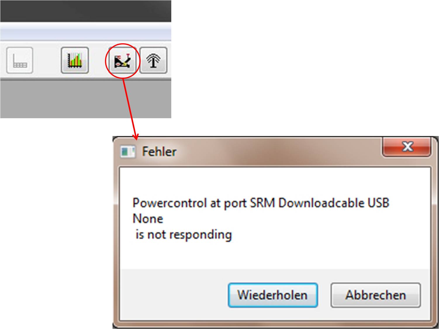
- 2.8 Error - PCIV at port SRM Downloadable USB None is not responding
- 3 Ergometer
- 4 Torque
- 5 Software
Power supply

The power supply has been designed to control the magnetic field in the eddy current brake of the ergometer very quickly. The operating mode of the power supply is indicated by a green LED, the control activity by a yellow LED. The yellow LED flashes briefly when the power supply is switched on and flashes continually during the isokinetic mode.
Why does the green LED not light up when switching on the power?
If the green LED does not light up after switching on, the power supply is probably defect.
| Possible causes | Solutions |
|---|---|
| Mains voltage (220 Volt) is not available. | Check the mains voltage.
|
| The power supply electronics are defect. | Please send the power supply to SRM for service.
|
| Cables to the ergometer or to the mains plug are damaged. | If the fuse of the power supply is only switched on when the ergometer is connected to the power supply, the fault is most likely inside the ergometer. In this case, please contact us.
|
Why does the yellow LED not light up briefly when switching on the power?
When the power supply is turned on, the yellow LED should light up briefly. If this is not the case, the fuse of the power supply could be blown.
| Possible causes | Solutions |
|---|---|
| Mains voltage (220 Volt) is not available. | Check the mains voltage.
|
| The fuse of the power supply electronics is blown. | Please send the power supply to us or change the fuse of the power supply (220 Volt, 1.6 Ampere). Please note that both phases are protected.
|
| The power supply electronics are defect. | Please send the power supply to SRM for service.
|
PowerControl IV (PCIV)

The Power Control IV takes care of the processing of the measurement values, the control of the power supply unit for the eddy current brake and the signal transmission by means of a serial interface to the PC. For basic information, see PowerControl IV.
Why does the PCIV not switch on?
The PowerControl IV does not switch on automatically when the power supply is switched on.
| Possible causes | Solutions |
|---|---|
| The power supply is defect. | Please check if the green LED is lighted after switching on the power supply. If it is not lighted, please check the power supply (see component power supply).
|
| The PCIV is not connected to the ergometer. | Please check all the cables carefully and plug them in. Observe the pin assignments of the different cables (see pin assignment).
|
| Individual pins on the PCIV connectors are bent or damaged. | Please contact us.
|
| The cable from the ergometer to the PCIV is damaged or possibly broken. | Please contact us.
|
| The battery of the PCIV is completely discharged. | Charge the PCIV by switching on the power supply.
|
| The PCIV battery can no longer be charged. | The battery of the PCIV may be defect. Please send the PCIV to SRM for service.
|
Is the PCIV compatible with Windows 8?
Yes. This requires an adapter cable (USB to serial interface) (USB/Serial Adapter).
Why does the PCIV not respond?
There may be a problem with the connection between the keyboard and the electronics in the PCIV. Please fill out a service form and send it to your SRM service center with your PCIV.
Why is the power output on the PCIV not displayed correctly?
| Possible causes | Solutions |
|---|---|
| The zero point of the PowerMeter is not set correctly in the PCIV. | Set the zero point correctly in the PCIV.
|
| The slope of the PowerMeter is not set correctly in the PCIV. | Set the correct slope with the SRMWIN software in the PCIV. When fully discharged, the PCIV loses this value.
|
| Settings in PCIV Setup cannot be saved. | Set the values with the SRMWIN software in the PCIV. When fully discharged, the PCIV loses its values.
|
Why is there no zero point determination on the PCIV?
To set the zero point on the PCIV, both the PowerControl and the ergometer has to be switched on. Both can be switched on by means of a crank rotation at the ergometer. The zero point is then determined automatically at the PCIV. For setting the zero point, see also: Zero calibration.
Error - Could not find PowerControl at COM
- Verify that the USB driver is installed and functioning properly.
- Ensure that the correct USB cable is selected (SRM Online - Options - System - Powercontrol - Active Port)!
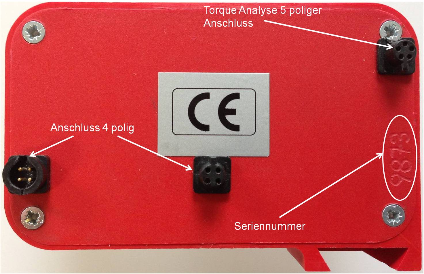
- Check that the PowerControl setting PCIV is set correctly in the software! (PowerControl IV)(PowerControl IV setting)!
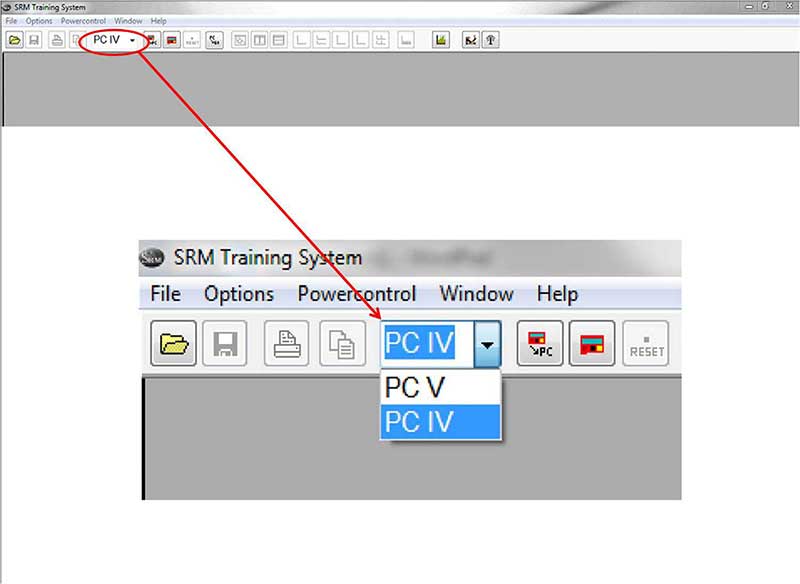
Error - Invalid PCIV password
- Please contact us and send the PCIV to SRM for service.
Error - PCIV at port SRM Downloadable USB None is not responding
Ergometer
Seating position
What are the possibilities to the seat post?
.jpg)
The names at the seat post can be found on the attached photo. If you need spare parts to the seat post, please leave us the correct names including the year of construction of the SRM ergometer.
If you have purchased a new saddle brace from us, you will receive the attached rulers from us. You would have to glue them yourself, so we can use your reference mass on your ergometer, e.g. Between the bottom bracket and the tip of the saddle.
What are the possibilities to the seat position?
The SRM ergometer allows individual adjustment of the athlete's sitting position. They can be adjusted individually by changing the position of the steering column, seat post and crank length.
The scaling of the seat post represents the distance from the center of the bottom bracket bearing to the seat tip. The following table shows the spans of the handlebar and saddle, the reference point is the center of the bottom bracket.
| Bezeichnung | Bewegungsebene | Spannweite |
|---|---|---|
| Sattel | horizontal | -15cm - 10cm |
| vertikal | 60cm - 85cm | |
| Lenker | horizontal | 35cm - 60cm |
| vertikal | 45cm - 65cm |
For more information about the positioning of the athlete click here.
Is possible to put on the ergo a seat post rail for carbon saddles?
Yes, you can change the upper part, the standard aluminum 27,2 mm bicycle seat post to a version for oval carbon rails.
Crank
Why do I here noise during cycling?
- Socket wrenches are not tight enough on the lengthenable cranks.
- Ergometer is not on a flat surface.
Fly masses
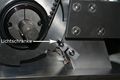
What is the function of the light barrier at the flywheels?
The light barrier measures the speed of the flywheels on the so-called interruption disk. It is obligatory for the calculation of the line. If speed is not measured correctly, the power output cannot be calculated. The displayed speed values in the SRMWin software - e.g. During a power test - do not correspond to real speed values.
The following figures show the position of the light barrier in the gearbox. The flywheels must be removed in order to clean the photocells or to change their position.
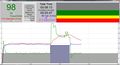
Speed display during a test (here 31,3 km/h)
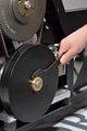
Removing the flywheels
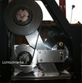
Position of the light barrier
Position of the light barrier at the interruption disc (open)
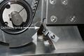
Position of the light barrier at the interruption disc (closed)


How to remove and mount the fly masses
The fly masses can easily be changed after taking off the left ergometer lid by loosening the brass-coloured counter-nut. Hand-tight fastening is enough. Always disconnect thee power supply from the Ergometer when opening the side covers! Never operate the Ergometer without the side covers! Before removing side covers insure fly masses have stopped spinning completely and use care when handling the fly masses to prevent injuries or bruises – both are very heavy!

- To remove/mount a fly mass you need the following tools: One or two aluminum spacer, Torx screwdriver an nut wrench (Fig.1)
- Open the cap of the Ergometer by removing the seven Torx screws (marked red) with the Torx T30 wrench (Fig.2)
- Use the nut wrench to rotate the brass nut counterclockwise (Fig.3). Hold the fly mass to counter the tool pressure if needed
- Remove the nut and pull the two fly masses off thee axle (Fig.4). Pay attention not to damage the threads on the axle
- Replace the SMALL fly mass with one aluminum spacer (Fig.5) or add two spacers when replacing the LARGE fly mass. Make sure the groove :in the spacer coincides with the feather key in the axle
Always insure the correct fly mass/spacer configuration: When installing both fly masses always add the SMALL fly mass first onto the axle. When removing the SMALL fly mass, add one spacer first, then add the LARGE flywheel. Same when replacing the LARGE fly mass – add the SMALL fly mass first and then add the two spacers. When testing without any fly mass remove all parts including the brass nut.
- To reinstall the fly mass on the axle (Fig.6) make sure the groove in the fly mass coincides with the feather key in the axle. This :groove will lock the fly mass an prevent thee fly mass from spinning free
- Using the nut wrench, rotate the brass nut clockwise until hand-tight (Fig.7)
- Make sure the fly mass sits firmly, has no play on the axle and can rotate freely! Remove all tools inside the gearbox! Reinstall thee :cover with the seven Torx head screws. Do not over tighten!
For more information about the fly masses see: Fly masses
PowerMeter
Why is there no braking power at the ergometer?
| Possible causes | Solutions |
|---|---|
| The power supply is switched off. | Switch on the power supply.
|
| The fuse of the power supply is blown. | Change the power supply fuse (220V, 1.6 Amp).
|
| The electronics of the power supply are damaged. | Check this by plugging in the power supply.
|
| The power supply is switched off by the software. | Switch on the power supply with software. Set control parameter / interface control (on-off) to on.
|
| The cabling of the ergometer is damaged. | Control parameters / Please contact us!
|
Why is there no braking power during the test?
The software switches off the power supply as soon as the pedaling frequency falls below 25 rpm for more than 3 s. If this happens it is possible to use the next solution. Do not stop during a test! Please program shorter intervals to reduce the idle time to the next stage, e.g. Instead of 4 min. 300 watt, 4 x 1 min 300 watt programming!
Why is it not possible to adjust the slope with the SRMWin software?
If there are any problems with the input of the slope in the SRMWin software (for example, faulty information, see error image), you can use the following troubleshooting solution:
The cause of this problem can be due to a wrong country setting of the hardware on which the SRMWin software is used. This is, for example, the case if an external medium is used for the SRMWin software and not the ergometer PC.
Different country settings can lead to variations in the input of numbers. This refers to the use of comma or dot as a decimal separator. For the slope setting, the point is to be used as a decimal separator!
The country setting can be changed as follows:
- Start button "Start".
- Search for "Region and Language" and then open it.
- Select "Location".
- Change the current location!
The country setting on the ergometer PC is: United Kingdom
For more information about changing country settings, please visit: Windows.Microsoft
Why are the performance or cadence data faulty?
The performance or cadence data are not displayed, fluctuate or are inaccurate.
| Possible causes | Solutions |
|---|---|
| The battery is almost empty or the PowerMeter board is damaged. | PowerMeter to the service incl. Battery change to us!
|
| Wiring the ergometer is not correct. | Please check all the cables carefully and plug them in. If this does not work please contact us!
|
| The cadence magnet is not in the correct position above the reed switch. | Please contact us!
|
| The specific slope has not been entered correctly into the PowerControl, or the PowerMeter does not transfer the correct specific slope to the PowerControl. | The zero point must be set!
|
Torque
What is the subsequent installation of the torque cable?
If you are the owner of an older ergometer, you can use the new Torque Analysis for Windows together with your ergometer. We recommend installing the corresponding sensor cable internally. The manual for laying is available at the following link:Manual Sensorkabel-Verlegung
Why do I get no/faulty zero-point detection with the Torque software?
The zero point determined on the PowerControl IV is not displayed or is displayed incorrectly during the automatic determination. Solutions are coming soon!
Software
Is the Ergometer software compatible with Windows 10?
Yes the software should be working with Windows 10 but there were some cases in which it did not. When connecting a new device to the system, Windows tries to automatically install a corresponding driver and update its version in future using Windows Update. In most cases, this approach is optimal as it guarantees installation of actual driver versions checked by Microsoft. In some cases, however, a user deliberately uses old driver versions and does not want them to be updated automatically by the system. It is possible to prevent this be turning off the driver updates in Windows 10: Driver updates Windows
Why do I get deviations between the set and actual cadence?
The cadence frequency in the isokinetic mode does not agree with a predetermined frequency from the presetting file.
| Possible causes | Solutions |
|---|---|
| Adjusted gear is not correct. | Please insert 9th gear.
|
| The translation ratio in the online setup is not set correctly. | Translation isokinetic test to 53/13.
|
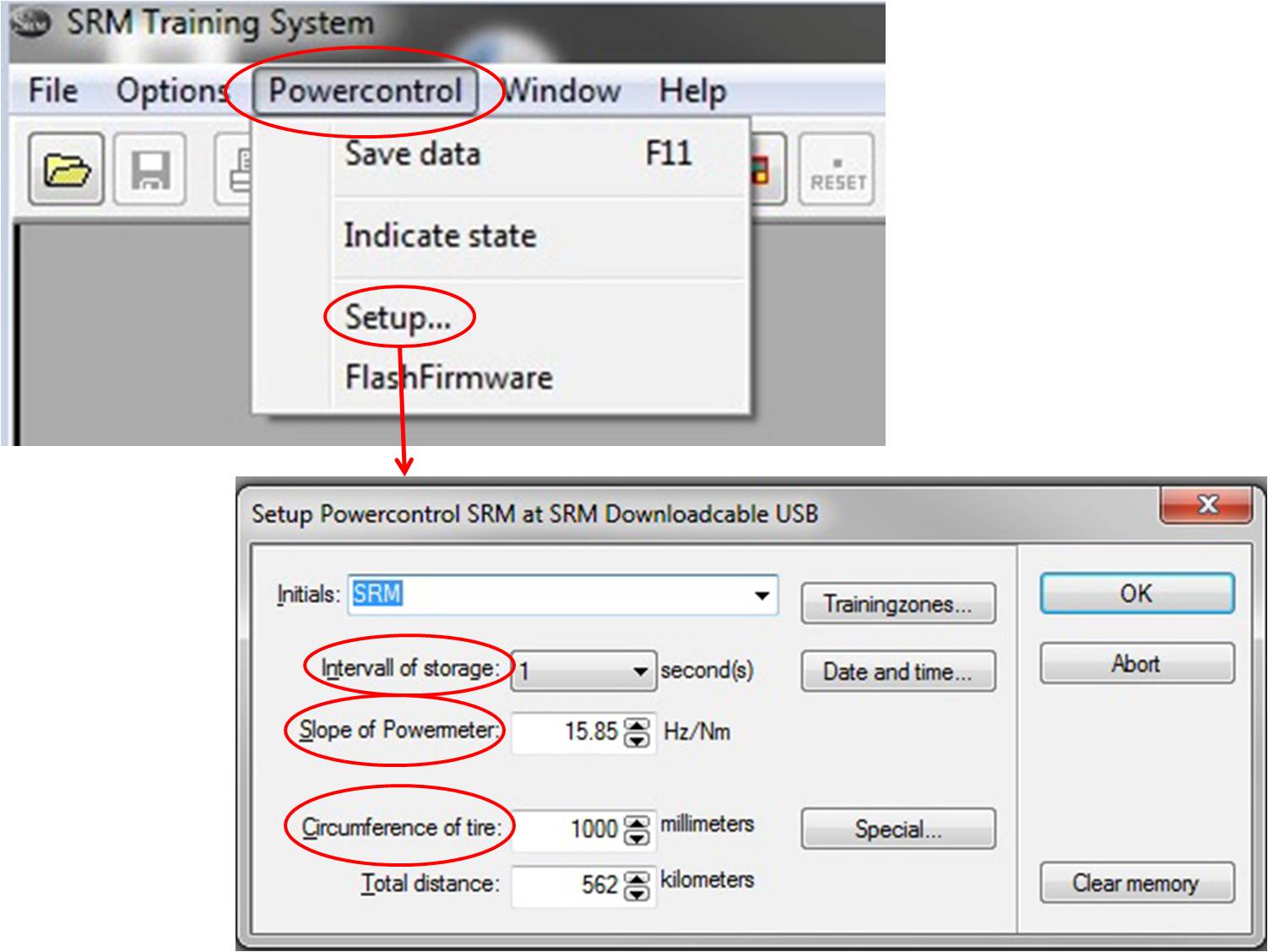
| Settings in PowerControl Setup, such as "Slope" or "Circumference of tire" can be changed, but not spoked. | The PowerControl has to be reset by us, please contact us.
|
Why do I get an incorrect display of speed?
The speed is not displayed or is displayed incorrectly. Solutions:
- Set the Laufradumfang (“Circumference of the tire“) to 1000 mm and select the preferred unit (metric or imperial).
- A light barrier in the gearbox measures the speed (speed) of the eddy current brake. If the light barrier is dirty or displaced due to the Vibarions, it must be cleaned and re-aligned. In rare cases it is defective and must be replaced.
Why do I het artifacts during heart rate measurements?
| Possible causes | Solutions |
|---|---|
| Unsuitable heart rate transmitter. | The following sensors are compatible with the PowerControl VI: Polar T31 Wearlink, Suunto Dual. The following sensors are compatible with the PowerControl 7: Suunto Dual, Garmin ANT +.
|
| Battery in heart rate transmitter empty. | Get new heart rate transmitter or change battery.
|
What use has a LogFile?
The LogFile of a test provides SRM with a range of information on the extent to which the ergometer works and where possible sources of error can be found. If problems with the function of the ergometer should occur, it is always helpful for SRM to get a LogFile in addition to the problem description. This enables SRM to quickly identify problems with the system and to provide feedback.
Please note the following for a LogFile:
- The LogFile (Testvalues.txt) can be found under the path: "C: \ Users \ Public \ Documents \ SRM \ _data.srm \ OnlineTestvalues \"
- The LogFile of a test is overwritten when a new test is started. Therefore, the LogFile of a particular test must always be copied and exported directly after the test.
If you experience a problem with the ergometer and you send us a log file, proceed as follows:
- Run a short step test with approx. 3-4 steps (start, for example at 80 W, duration 3 min / step, gradient 20 W)
- Capture a screenshot
- Export the SRM training files
- Copy / export the LogFile
- Allow both SRMs
For example, a LogFile to SRM is as follows: Example LogFile